
Personal Project · 2026 · In Progress
USB-C Speaker & Discrete Loudness Meter
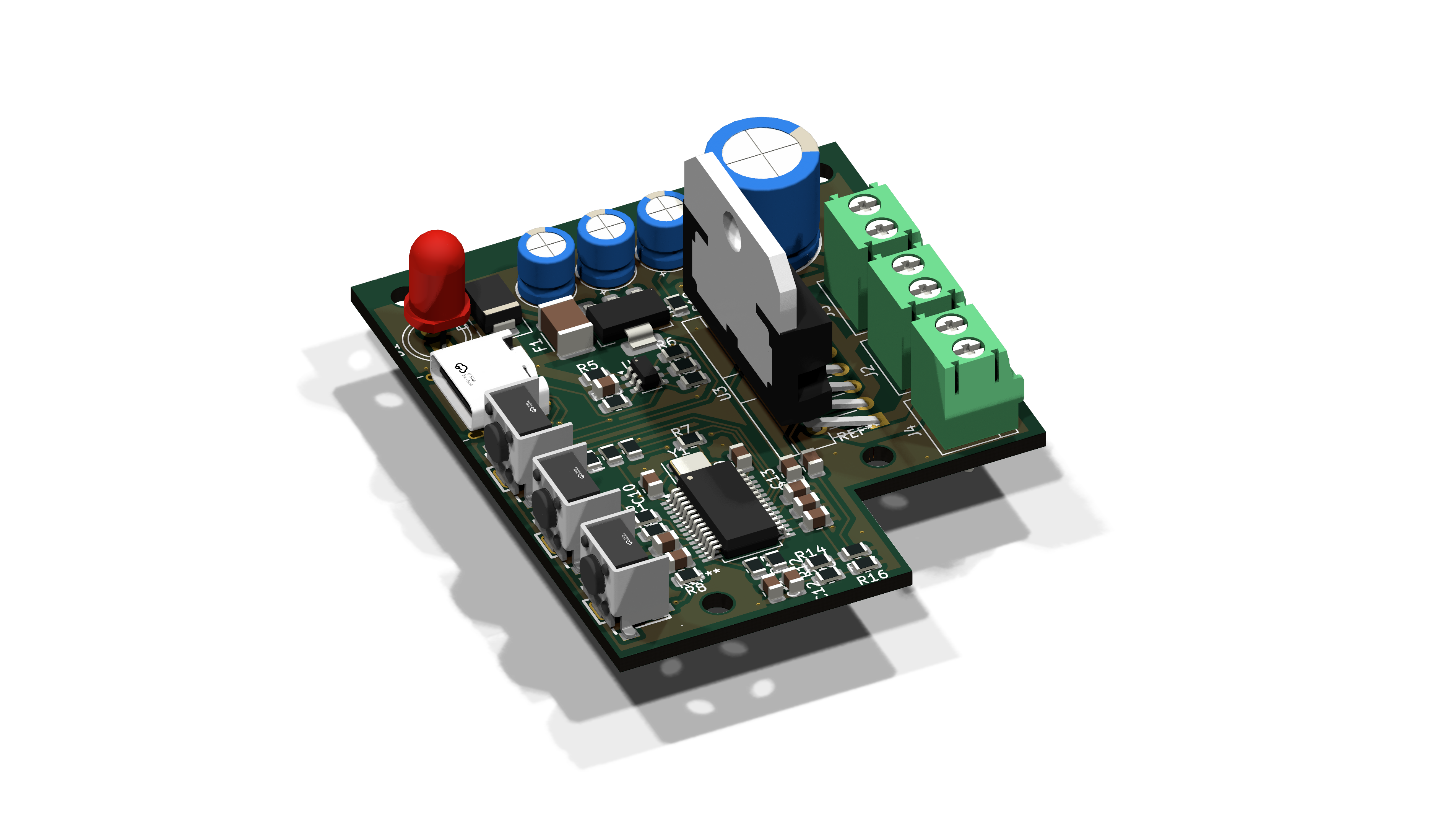
A two-board speaker system that runs off a single USB-C cable. The amp board enumerates as a USB sound card and negotiates 12V over PD, and the loudness meter drives ten LEDs per channel using discrete transistors instead of a driver IC. These are the first PCBs I designed. The end goal is everything mounted in a custom speaker housing.
The Idea
Desktop speakers usually mean a wall adapter, an aux cable, and a premade amp module. I wanted to build the whole signal path myself and have it run off one cable: plug in USB-C and the board shows up as a sound card, negotiates its own power, and drives the speakers directly.
The other goal was the skill itself: I had never designed a PCB, and I picked this project specifically to learn. KiCad was the obvious tool, since it's free and does everything from schematic capture to the fab files JLCPCB builds from.
The Signal Chain
One connector carries everything. The data lines go to a PCM2704, which any computer sees as a class-compliant USB sound card, so no drivers are needed. On the power side, a CH221K requests 12V from a USB-C PD supply for the amplifier, and an AMS1117 steps that down to 3.3V for logic. The loudness meter taps the analog signal right before the speakers.
The Amp Board
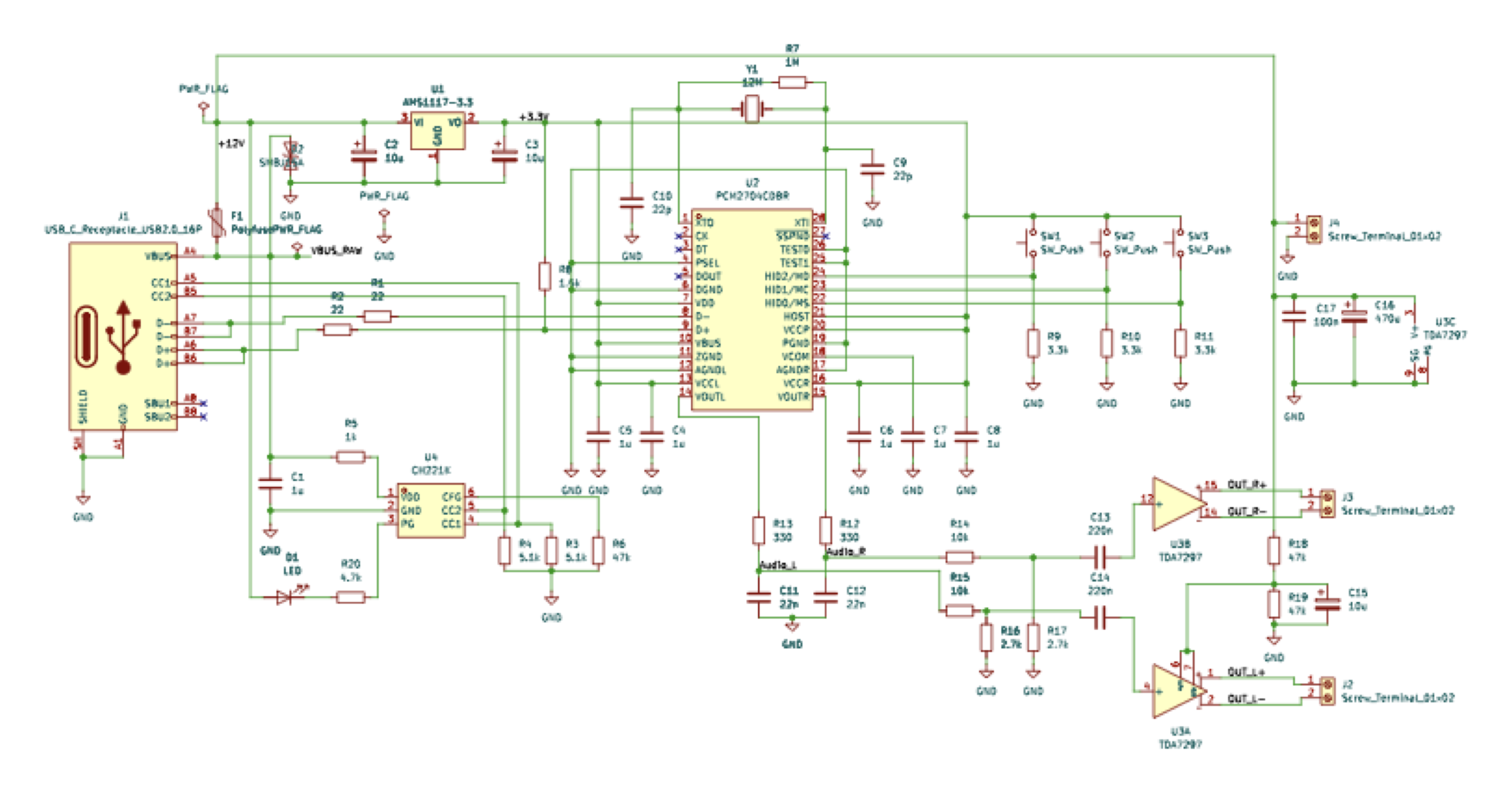
The amplifier is a TDA7297, a 15W×2 class-AB chip running directly off the 12V rail. Input protection is a polyfuse for overcurrent and an SMBJ15A TVS diode to clamp transients on VBUS. A crystal clocks the PCM2704, and the on-board volume buttons connect straight to it, since USB audio handles volume in the stream.
This is also the first schematic I ever drew. I did not know yet that net labels tie nets together, so every connection is a drawn wire. It works, and I left it unretouched. Schematic PDF →
The board went through four fabbed revisions. JLCPCB assembled the SMT parts, so each spin was cheap and fast enough to just order, test, and fix in the next version.
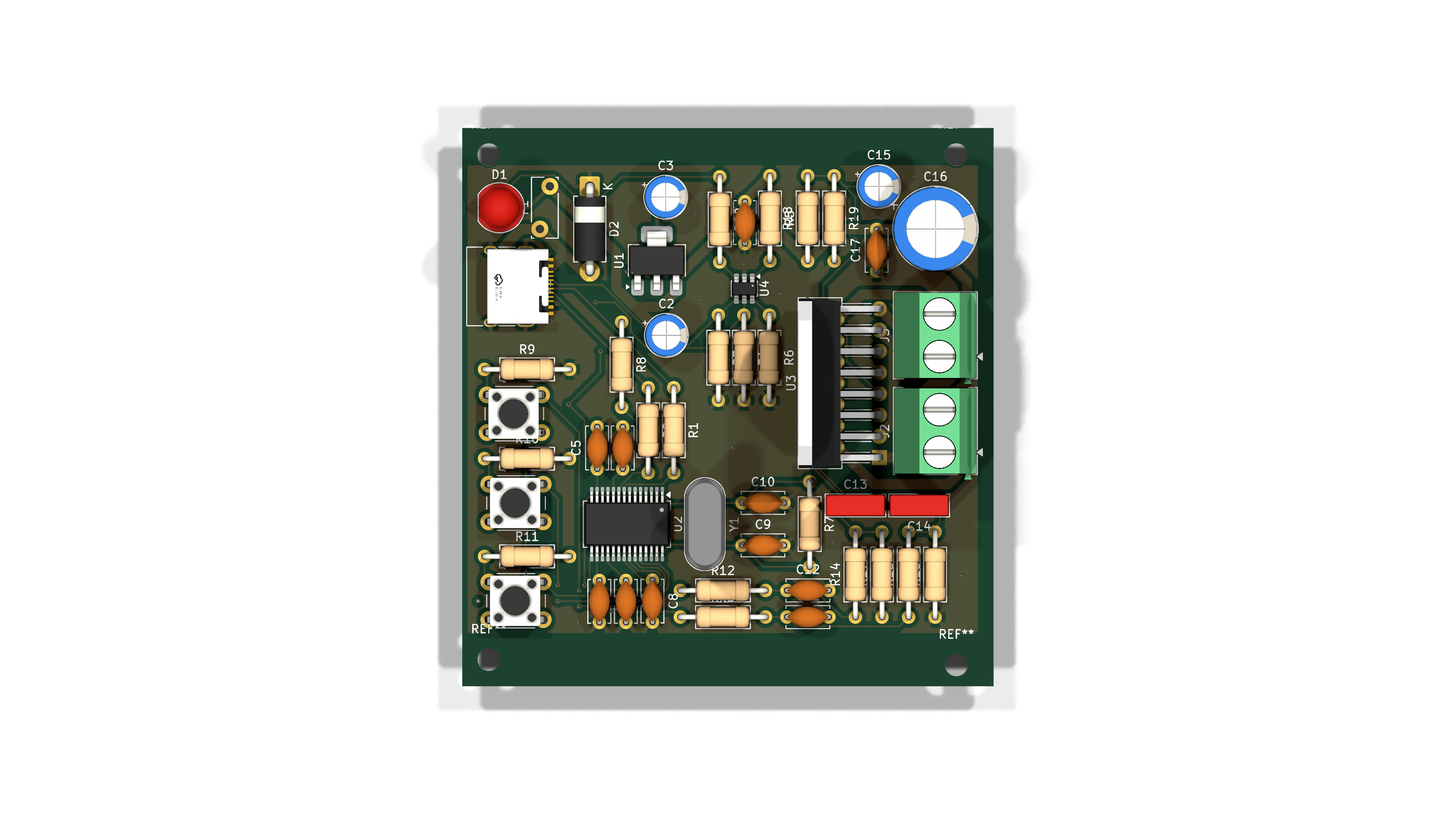
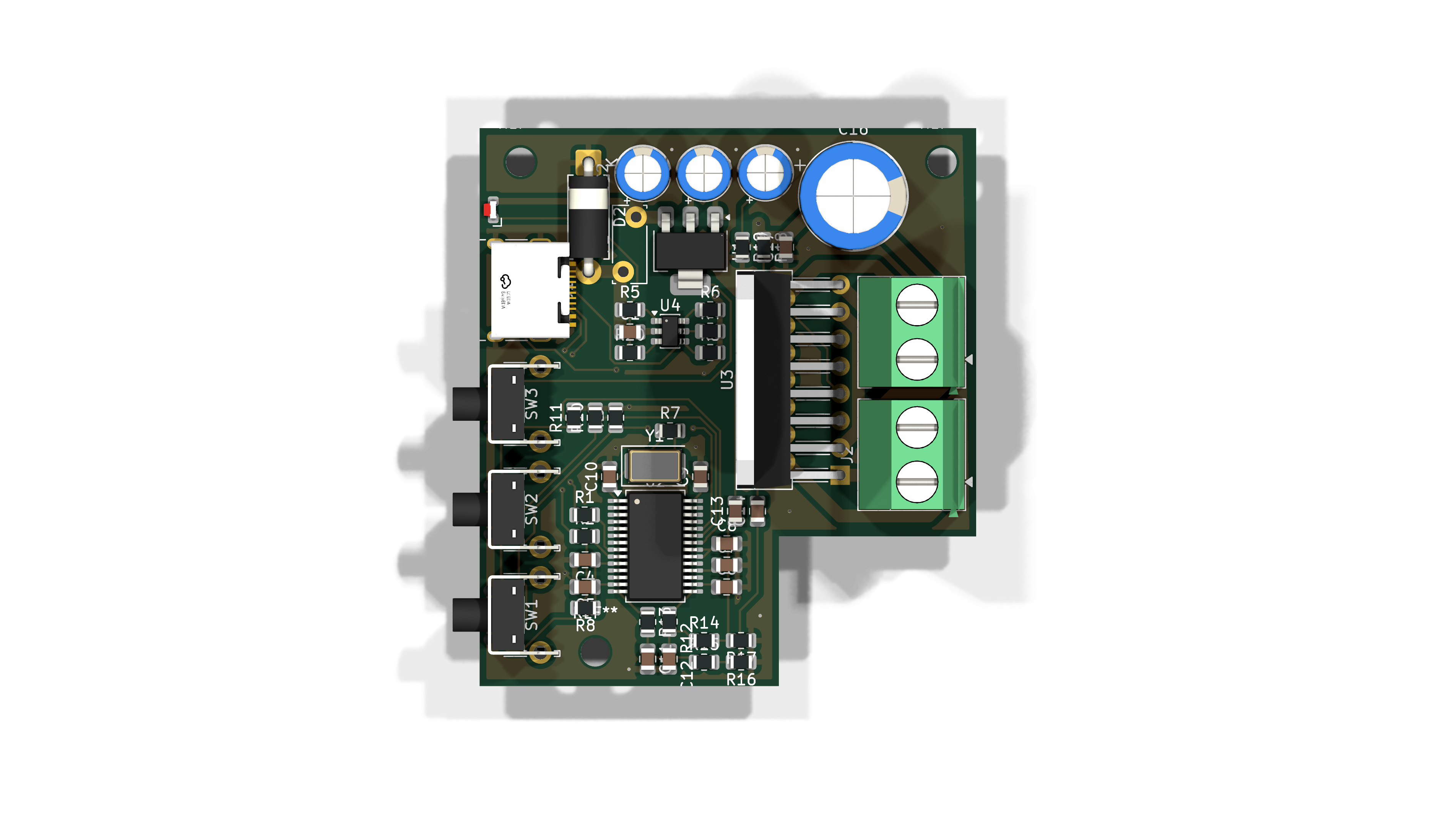
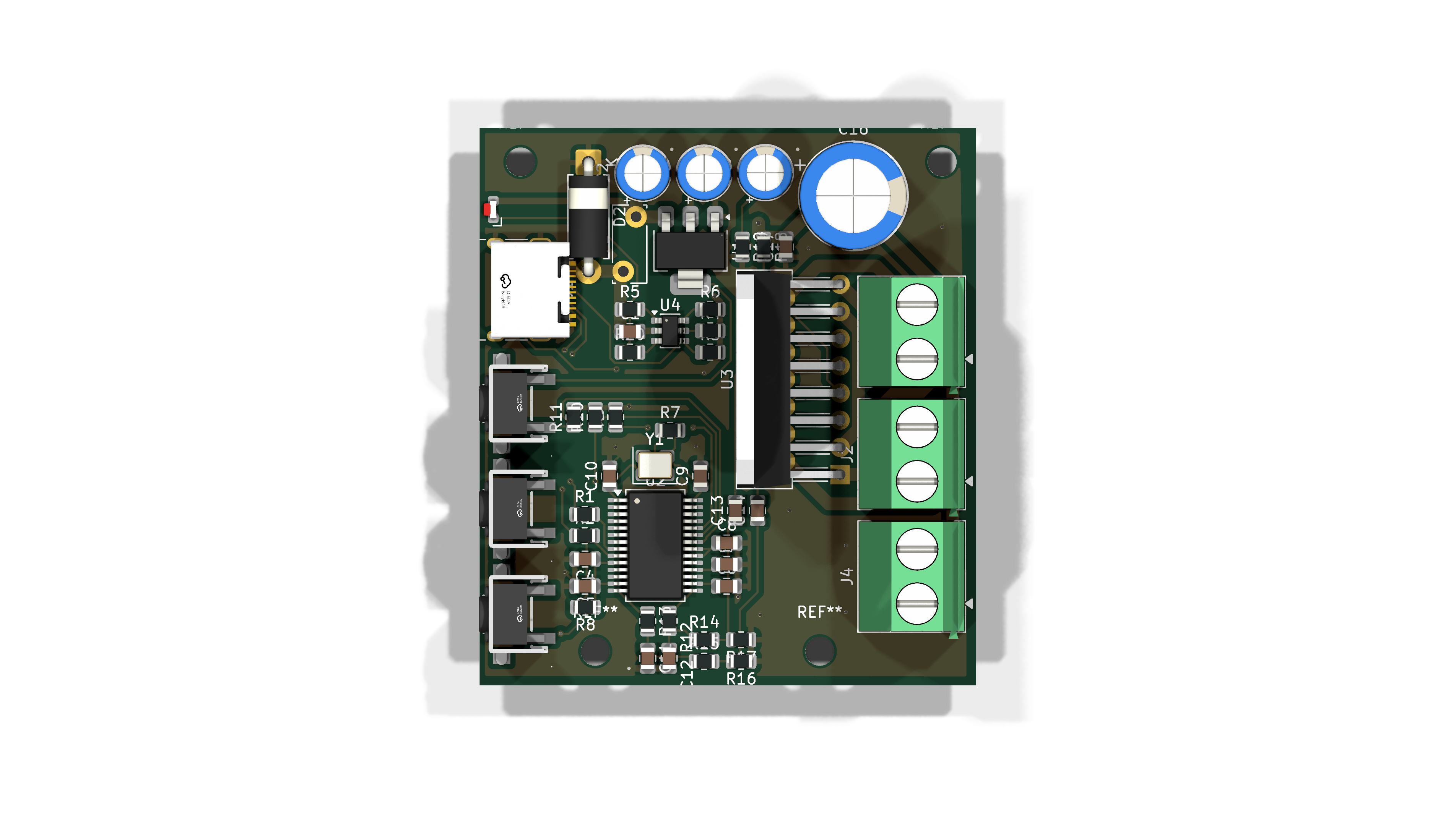
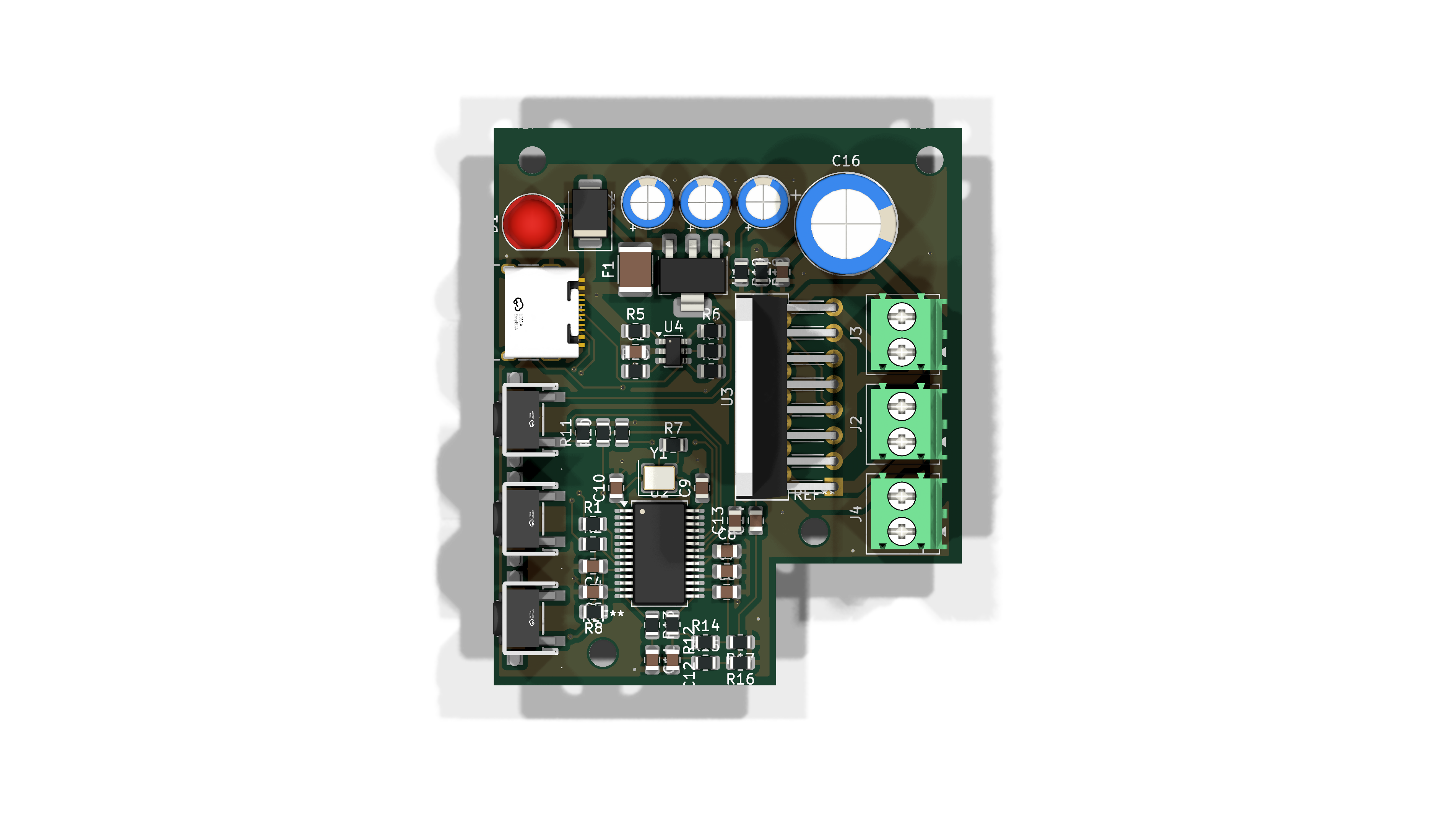
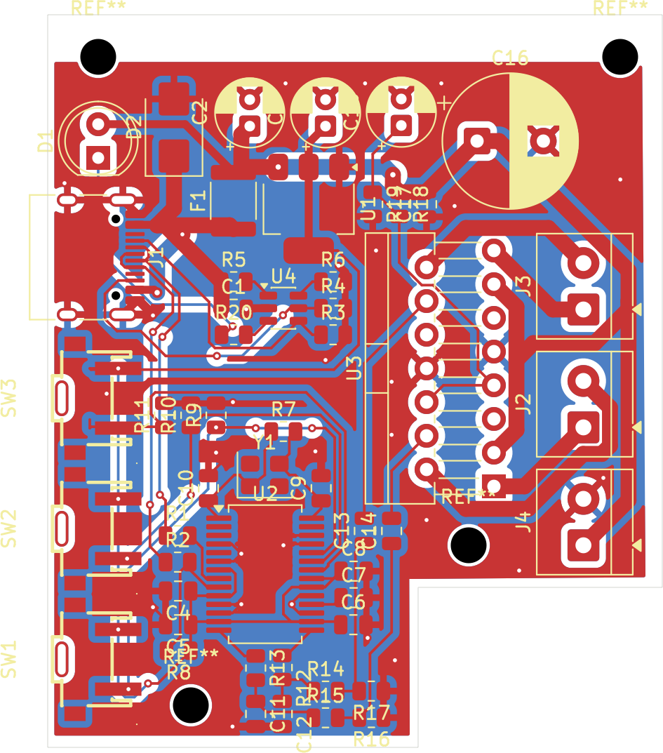
The layout follows the signal: the USB data pairs and crystal stay close to the PCM2704 on one side, and the 12V power path and speaker outputs stay on the other.
The Loudness Ladder
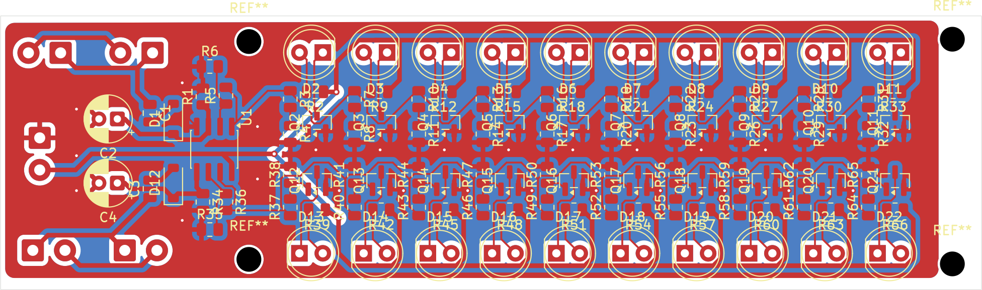
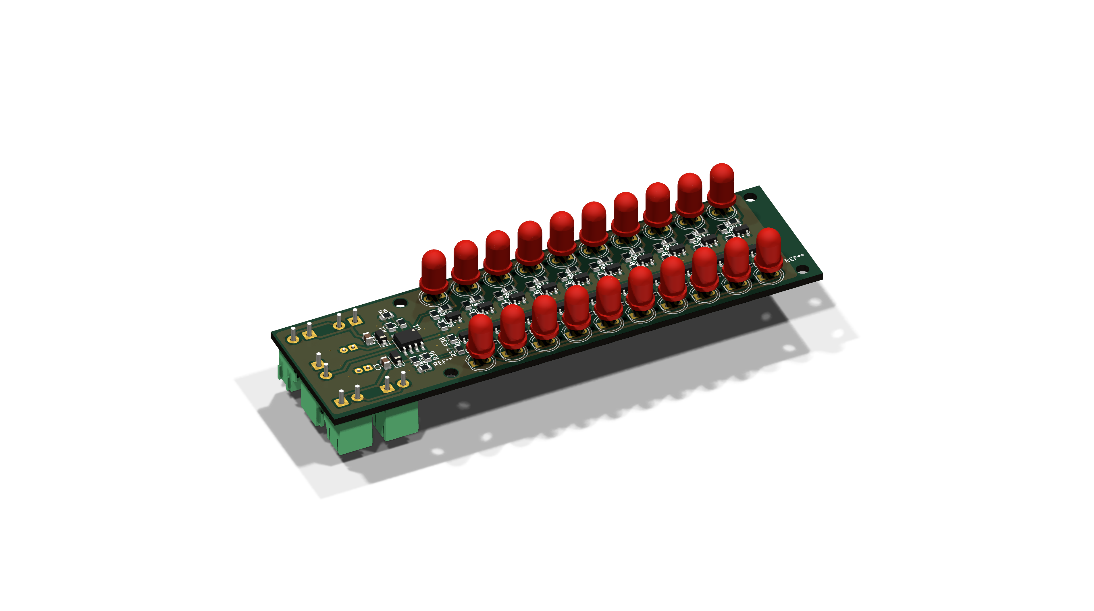
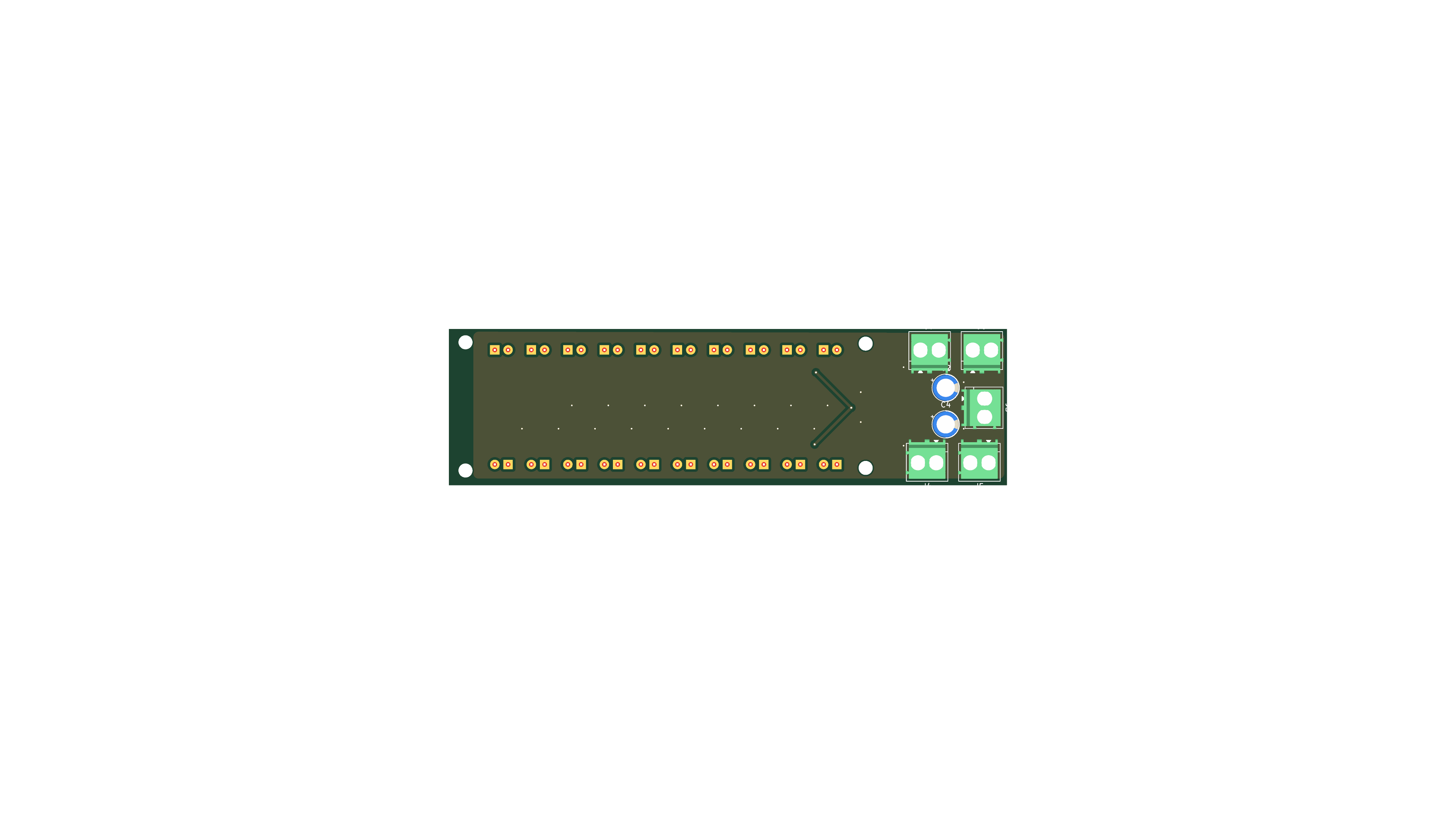
The second board is a stereo loudness meter: ten LEDs per channel that light in sequence as the music gets louder, with the top LED doubling as a clip indicator. Driver ICs exist that do exactly this, but I built it from discrete parts instead. Per channel, half an LM358 works as an envelope detector and gain stage, and each LED has its own MMBT3904 with a base divider that sets its turn-on threshold. Functionally this is a flash ADC: ten threshold stages compare the same input in parallel and output a thermometer code. The difference is that the code drives LEDs directly instead of being encoded into bits, and the thresholds are spaced by loudness rather than equal voltage steps.
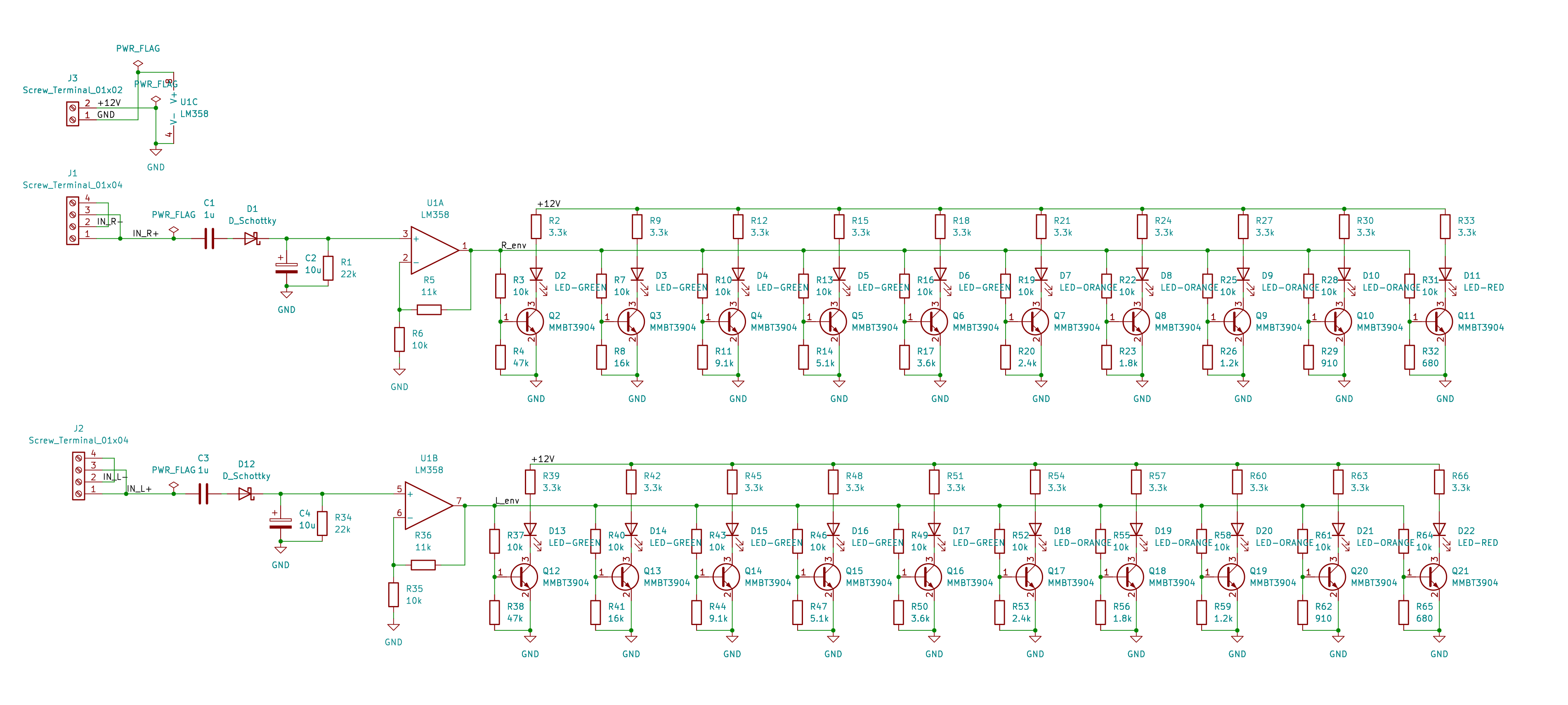
This is my second schematic, drawn after the amp's. Compared to the first one it uses net labels instead of drawn wires everywhere, and the signal path reads left to right in stages. The improvement between the two boards is what I picked the project for.
The interesting part is sizing those twenty resistor dividers. LEDs should light at equal loudness steps, and loudness is logarithmic, so each threshold sits a fixed number of dB below full scale, then gets snapped to real E24 resistor values. I derived the whole thing by hand and wrote it up: envelope detector ripple, the op-amp gain choice, the dB spacing, and the error introduced by E-series rounding. Full derivation PDF →
Input
USB-C, one cable
Power
12V via USB PD
Audio In
PCM2704 USB DAC
Amplifier
TDA7297, class AB
Drivers
Dayton CE81PF-8
Meter
20 LEDs, no driver IC
Amp Revisions
4 fabbed
Meter Revisions
2 fabbed
Next: The Housing
Both boards are fabbed, and the drivers are picked out: Dayton CE81PF-8 full-range units, already modeled in CAD. What's left is the enclosure that mounts the drivers and both boards, with the LED ladder as the front face. I'll update this section with photos, measurements, and a demo video as the build progresses.