
R&D · 2025
Cycloidal Drive
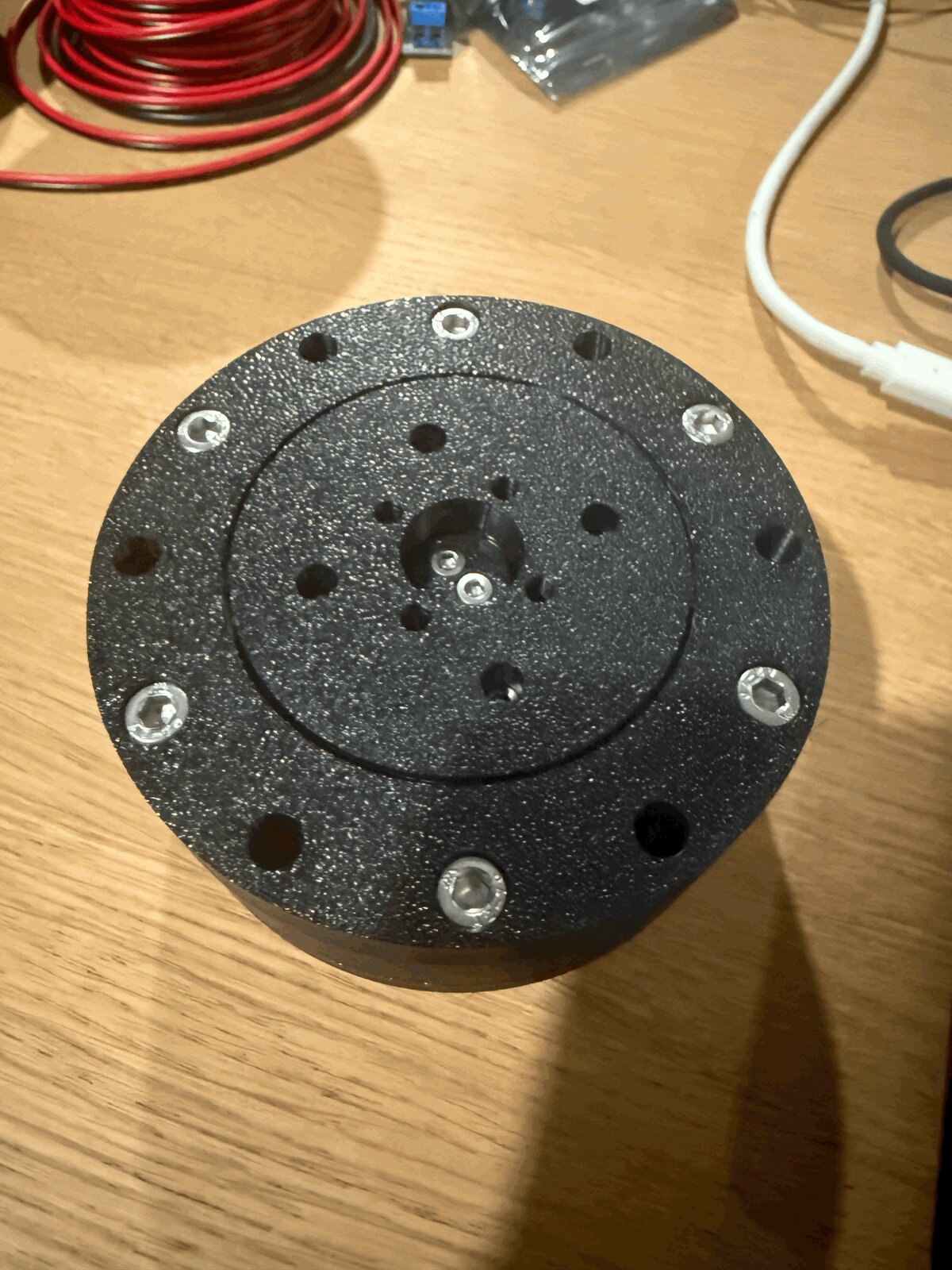
A 3D-printable cycloidal gearbox in two iterations: a 12:1 proof-of-concept, then a 26:1 redesign for the robotic arm's joints. The exercise was about how cheap you could go. Every bearing is steel balls in a printed PETG raceway, and total BOM lands around $20 per drive.
Why Cycloidal?
Cycloidal drives pack high gear ratios into compact, flat housings. Perfect for a 3D-printed robotic arm where every millimeter of joint thickness matters. Unlike planetary gearboxes, the cycloidal mechanism distributes load across multiple contact points simultaneously, giving good rotational backlash characteristics even with printed parts. And critically for this project, the geometry is printable without requiring tight tolerances on gear teeth.
V1 – The Proof of Concept
The first version was a 12:1 drive (12-lobe disc, 13-pin ring) built to validate the concept. Almost entirely 3D-printed in PETG with only two off-the-shelf radial bearings for the eccentric shaft. The output bearing was custom: a printed raceway loaded with 24× 6mm steel balls. It spun smoothly by hand but had noticeable backlash. Good enough to prove the concept, not good enough for the arm.
Ratio
12:1
Diameter
100mm
Height
30mm
COTS Bearings
2 (eccentric shaft)
Output Bearing
Custom (24× 6mm)
Material
PETG
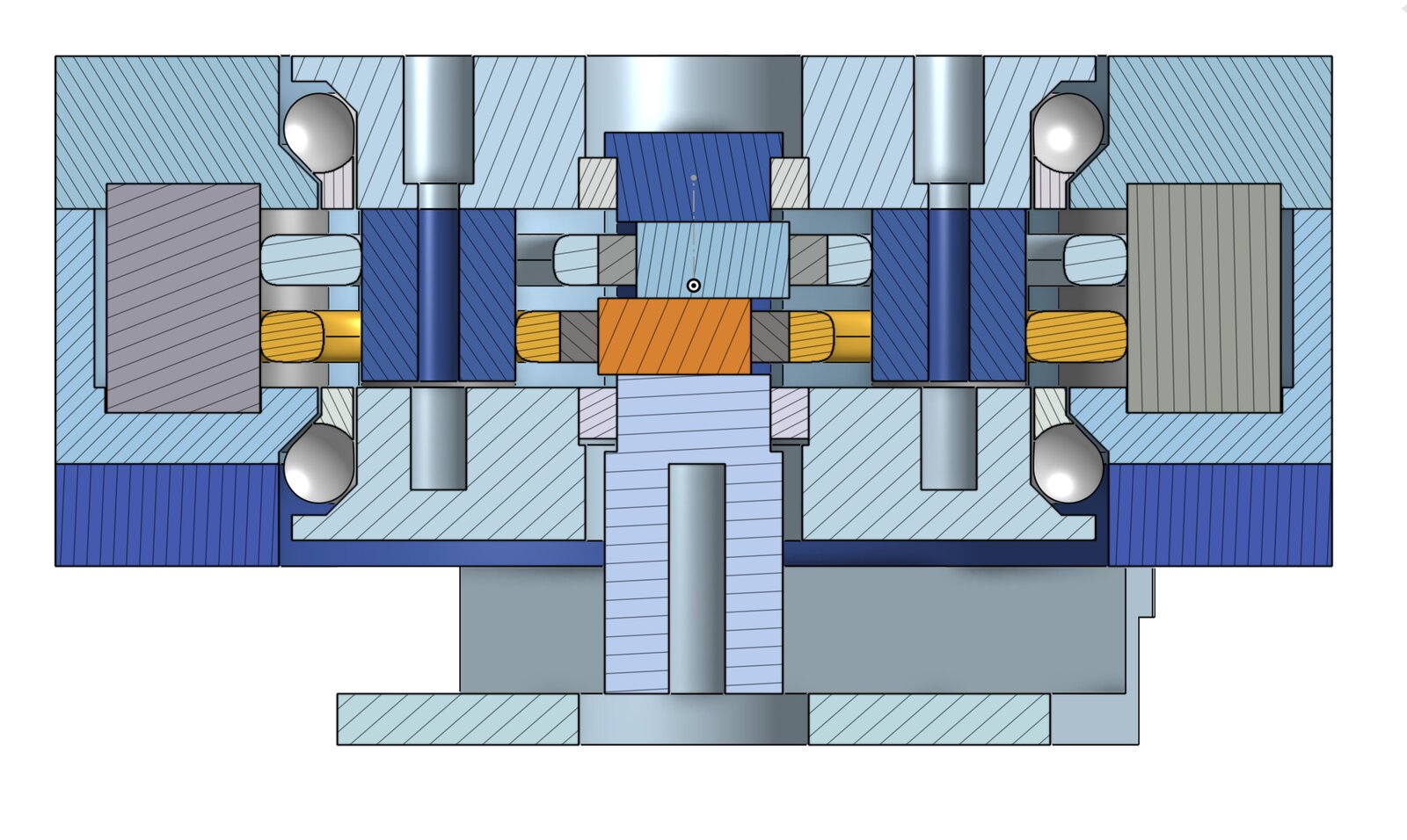
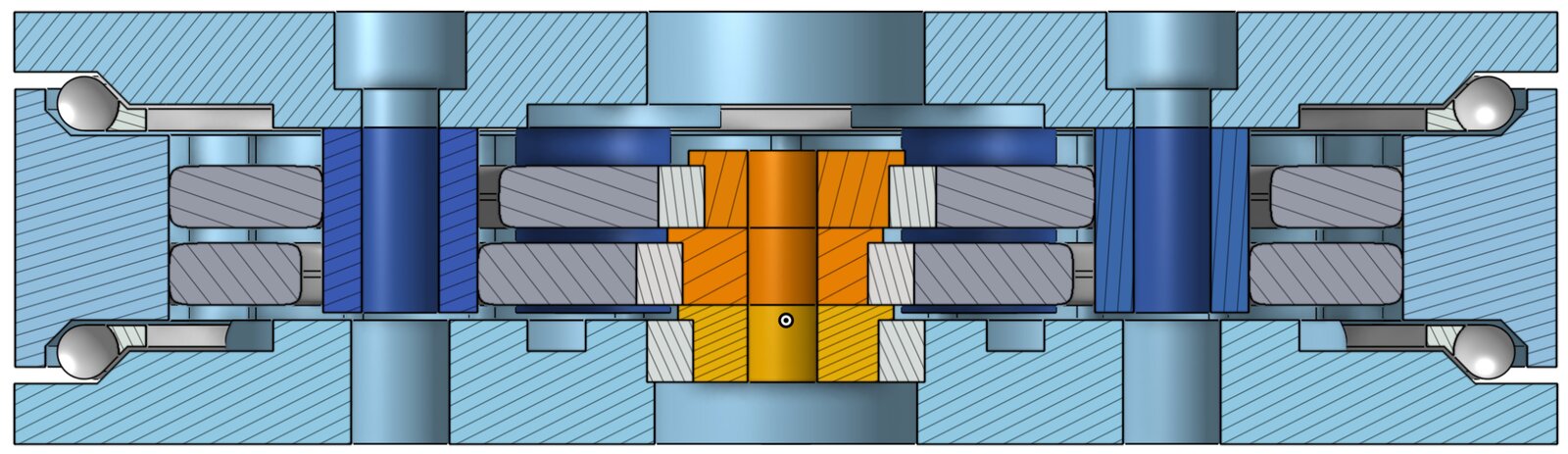
V2 – For the Arm
V2 was redesigned specifically for the robotic arm's joint modules. The ratio jumped to 26:1 for more torque, and the stack height was slimmed from 30mm to 20mm. The biggest change: the housing now doubles as the output shell, so arm links bolt directly to the rotating housing while the output pins stay fixed to the motor. This eliminated a separate output stage and made the whole joint more compact.
The Bearing Tradeoff
The core lesson from this project was about custom vs. commercial bearings. The 3D-printed raceways needed to be adequately tight to control axial backlash, but that tightness created friction that reduced torque transfer from the motors. Rotational backlash was actually not bad (cycloidal drives are inherently good at that), but the axial friction meant the joints were torque-inefficient overall. Bulk 4mm steel balls cost $10 on Amazon and lasted the entire project, so the cost savings were real. But premade metal ball bearings would have been a significant quality-of-life and performance improvement. The experiment answered the question it was designed to answer.
Cost Breakdown
Steel Balls
$10
PETG Filament
~$5/drive
Eccentric Bearings
~$3
Fasteners
~$2
Total per Drive
~$20