
UPenn ESE 3500 · Fall 2026
Wireless RC Cars
Our ESE 3500 final project. My team bought two cheap RC car kits, kept only the motors, and rebuilt both cars around STM32 boards with a wireless joystick controller we made ourselves. The plan was for one car to chase and catch the other using infrared.
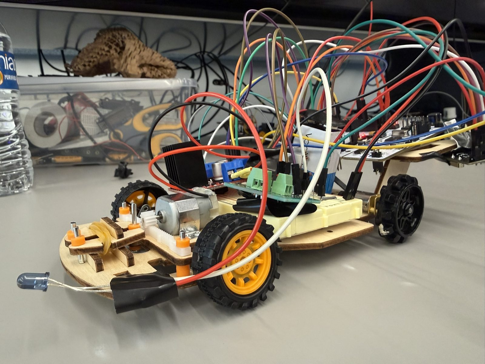
The Idea
Each kit came with two DC motors: one drives the rear wheels, and the other turns a small gear against a rack to steer. Everything else we added ourselves, including the microcontroller, motor driver, radio, and controller.
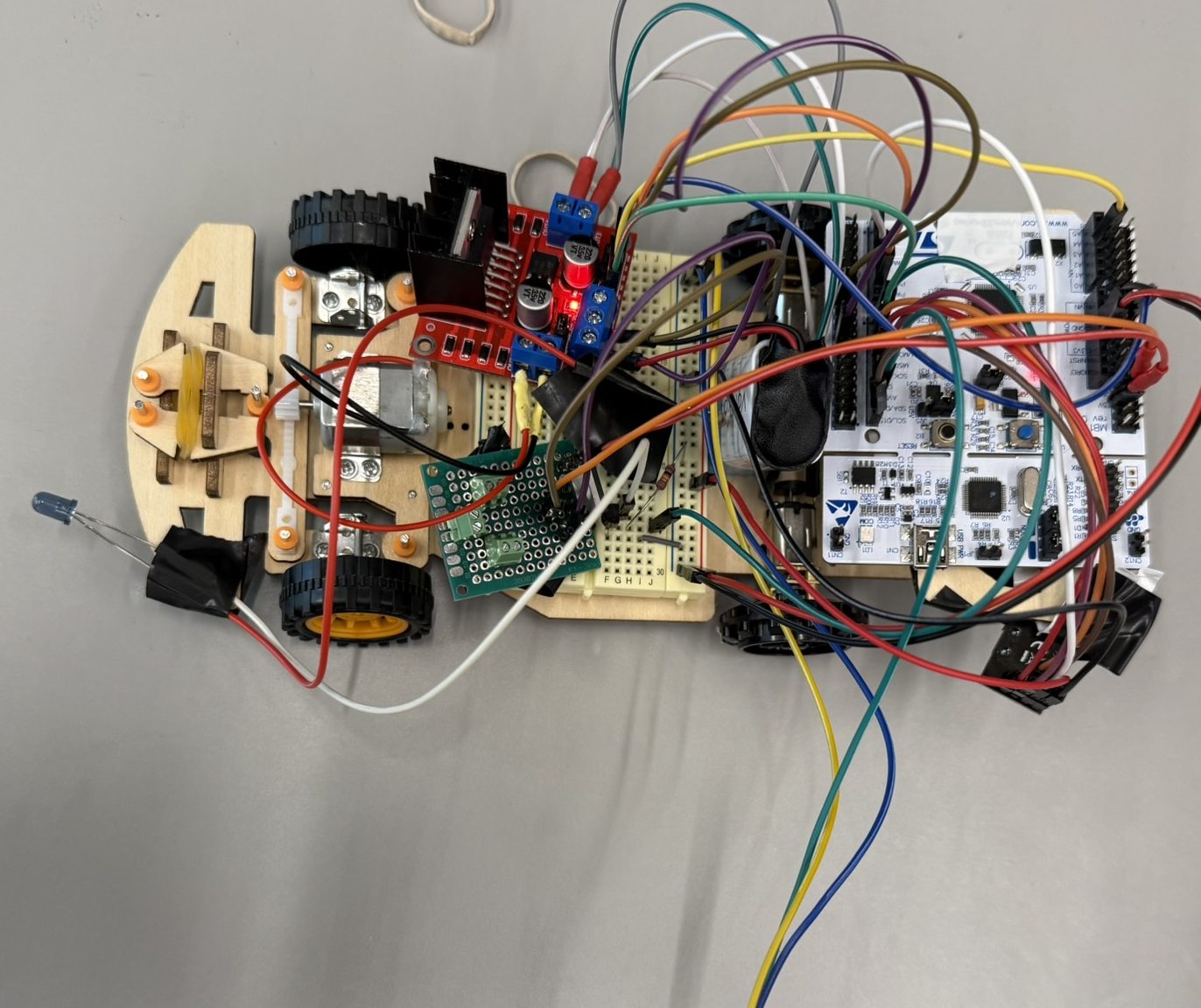
We built two cars for a game of tag. One car carries an IR LED and the other an IR receiver, and the game ends when the chaser picks up enough IR to count as a catch.
Driving It
How It Works
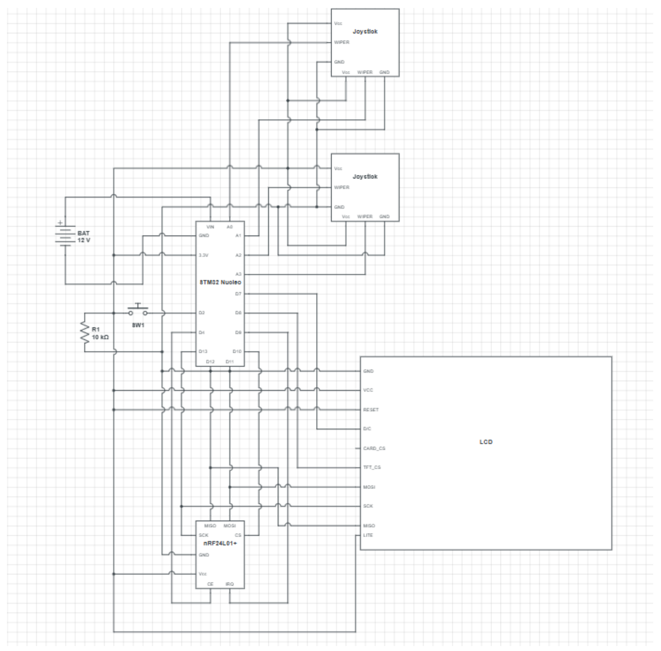
The controller is two potentiometer joysticks on a breadboard. An STM32 reads them with its ADC and sends the stick positions over an nRF24L01+ radio in the 2.4 GHz band. On the car, a second radio passes the packets to another STM32, which drives the H-bridge with PWM. A 5V regulator powers the logic from the 9V battery.
I focused on the hardware and my teammates led the firmware, which was extensive. We wrote drivers for every component, including our own packet format for the radio, and nothing was encrypted. Since the wiring and the firmware depended on each other, we tested and debugged the cars together.
Getting It to Move
For a while the cars wouldn't move at all, and power was my part of the project. Every board we added was weight the kit motors weren't designed to carry. Two AA cells didn't give the motors enough power to move the car. Adding more AAs raised the voltage, but the extra cells added enough weight that the car still stalled.
2× AA
~1.5 W · stalled
Each cell supplies about 0.5 A steadily at 1.5 V
4× AA
~3 W · stalled
More power, but four cells were too heavy for the motors
One 9V
~3.15 W · moves
About 350 mA for an hour from one light cell, then the voltage drops off
AA cells hold more energy than a 9V battery, but they can't deliver it quickly. The car needed power more than runtime, so I chose 9V batteries and accepted that they would drain much faster. They were the only option that actually moved the car.
The IR Tag Game
The catch never worked reliably. The receiver's reading wasn't linear with distance and changed from one try to the next, so a fixed threshold couldn't tell a catch from noise.
At night it was inconsistent, which I think comes from the LED not emitting evenly in every direction. During the day it was unusable, because sunlight carries a lot of infrared.
If we did it again, I'd pulse the LED and compare readings with it on and off, so the constant background from the sun cancels out.
Steering mostly works. The steering motor spins faster than the rack needs, so the gear grinds against the rack at the ends of its travel.