
Personal Project · May–August 2025
6-DOF Desktop Robotic Arm
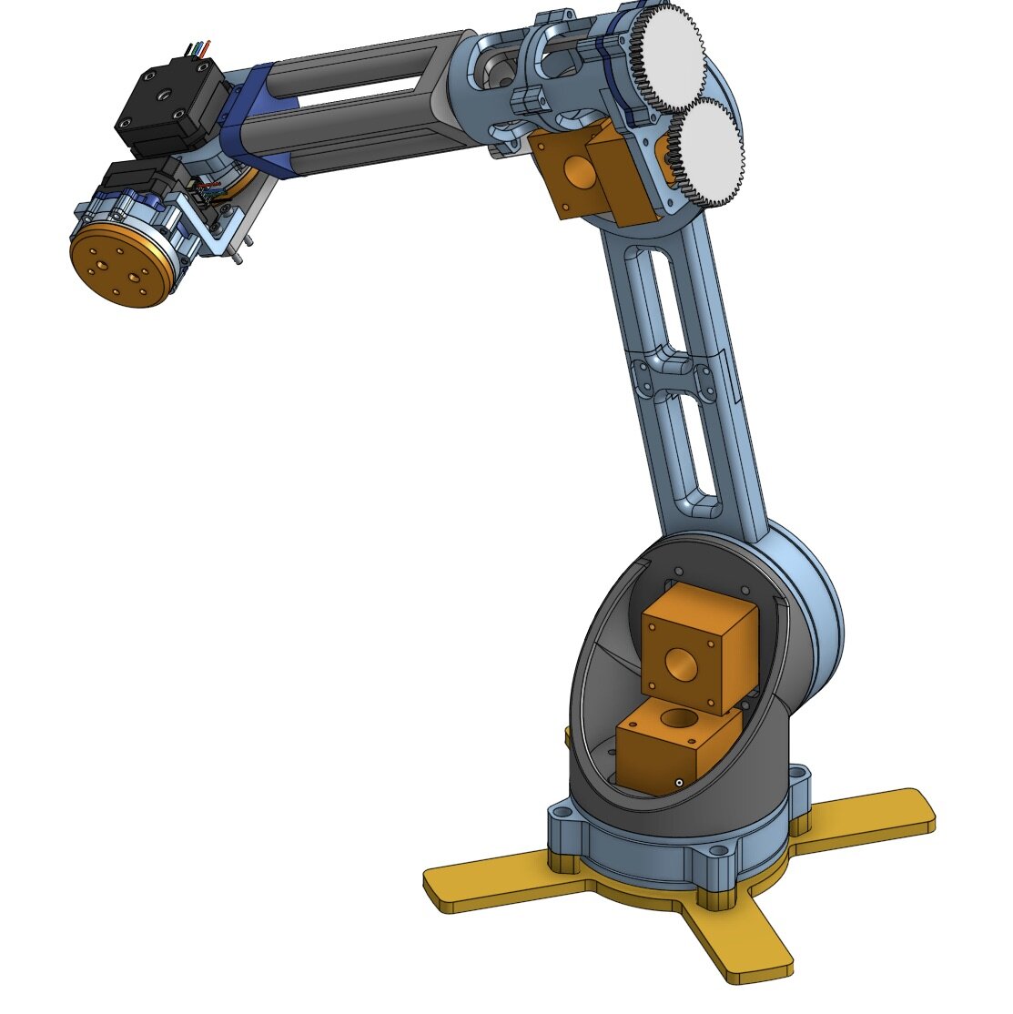
A solo six-DOF desktop arm spanning the full stack: cycloidal drives I designed from scratch, custom 3D-printed bearings, a Python IK solver and trajectory planner, Arduino motor firmware, and a browser-based control interface. The $10 bag of steel balls was the constraint that drove everything else.
The Challenge
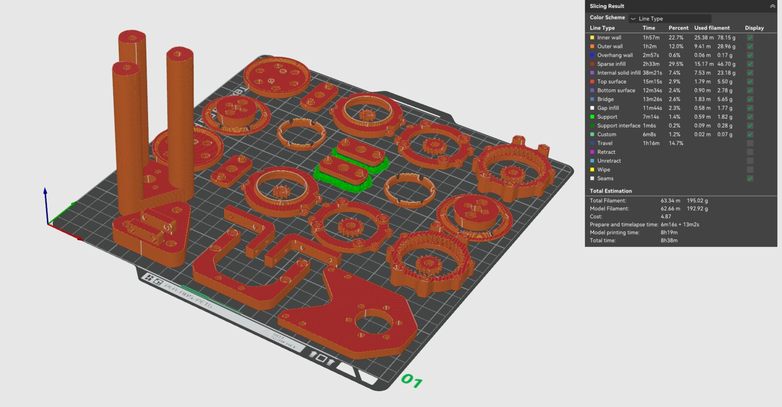
I wanted to explore robotics and set myself a constraint: build a robotic arm as cheaply as possible, with no premade ball bearings. I bought bulk 4mm steel balls ($10 on Amazon) and designed every bearing from scratch using 3D-printed PETG raceways.
Mechanical Design
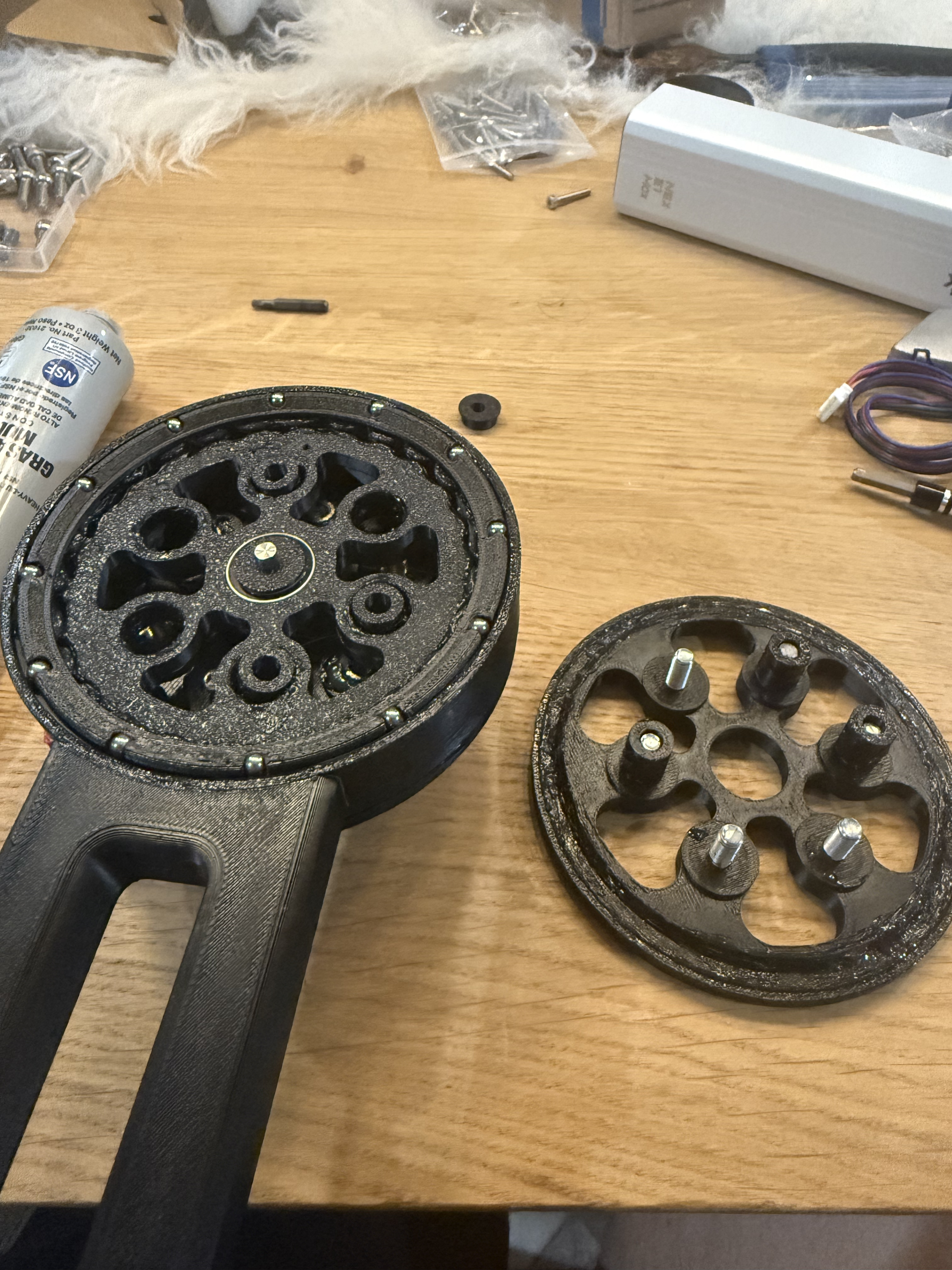
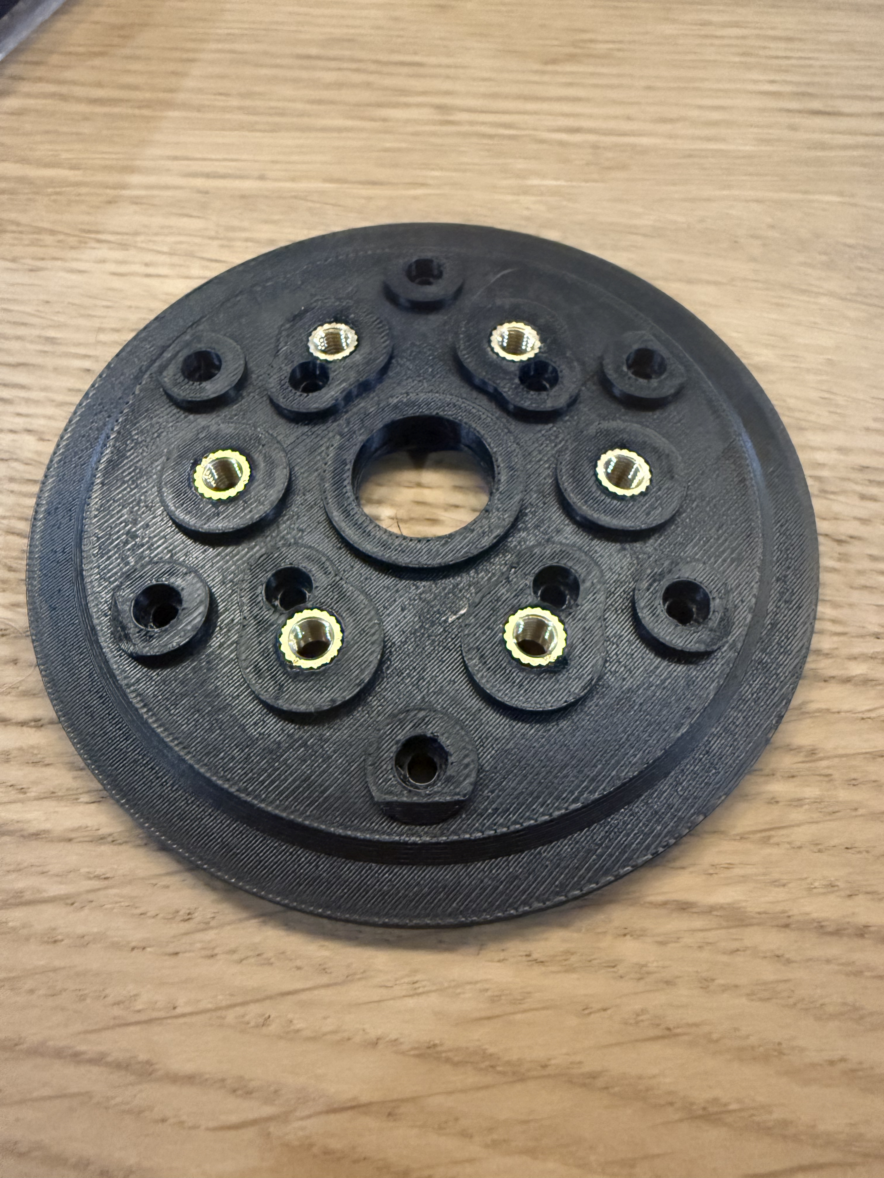
The arm uses two types of custom gear reductions: 26:1 cycloidal drives for the main joints (base, shoulder, elbow) and 5:1 planetary gearboxes for the smaller joints. Both use the same custom ball bearing design: 3D-printed raceways loaded with 4mm steel balls. The housing of each drive doubles as the output shell, so links bolt directly to it. Structure is PETG with weight-saving cutouts and M5 spine bolts for serviceability.
Reach
~80cm
Payload
0.5kg target
Gear Ratios
26:1, 5:1
Motors
NEMA 17 steppers
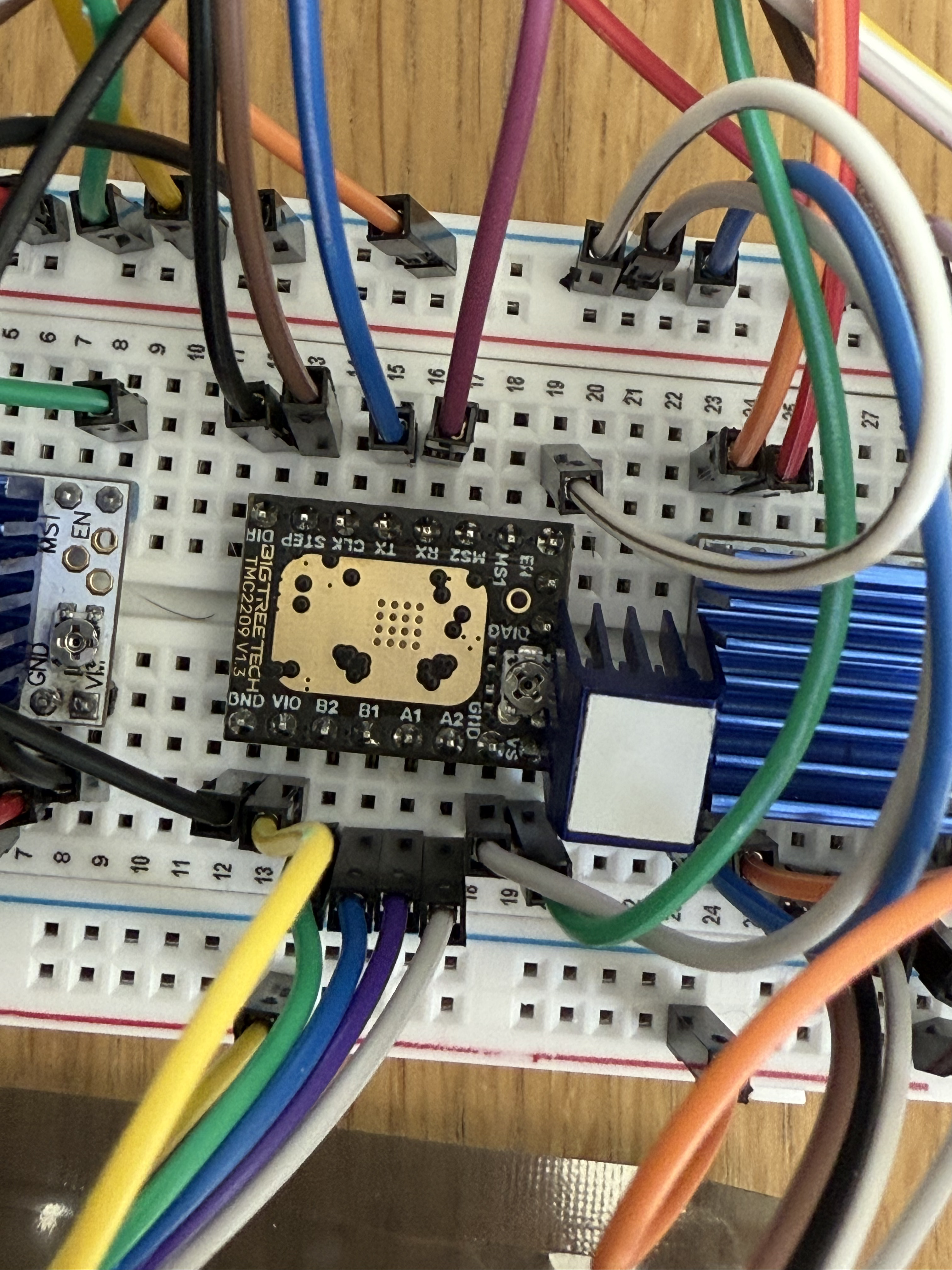
Drivers
6× TMC 2208
Controller
Arduino Mega
Material
PETG
Bearing Cost
$10 total
The planetary gearbox handles the wrist joints where compactness matters more than raw torque. Each gearbox shares the same custom ball bearing approach, steel balls in a printed raceway, keeping costs minimal while the geometry does the heavy lifting.
The base joint uses the 26:1 cycloidal drive where the housing doubles as the output shell. You can see the custom ball bearing inside, the 4mm steel balls sitting in the printed raceway. This is where the axial friction issue was most apparent.
Software Stack
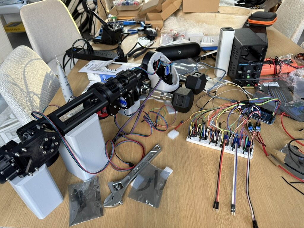
The software side was equally important. I programmed an inverse kinematics solver and trajectory planner in Python using the Robotics Toolbox, generating time-based joint commands. These get transmitted as step pulses to the motors via Arduino firmware I wrote in C++. I also built a web-based control interface using JavaScript, HTML, and CSS with Meshcat for 3D visualization, letting me set start/end positions, edit trajectories with bezier control points, cycle through saved paths, and commit movements to the arm.
What I Learned
The custom bearings worked mechanically but revealed a fundamental tradeoff: the 3D-printed raceways needed to be tight enough to control axial backlash, but that tightness created friction that ate into the motors' torque budget. Rotational backlash was actually fine (cycloidal drives are inherently good at that), but the joints were torque-inefficient overall. I shelved the project when the semester started because a redesign with premade metal bearings would have been needed. The $10 experiment proved what works and what doesn't.